![]()
| Applies To | |||
| Product(s): | STAAD.Pro | ||
| Version(s): | All | ||
| Environment: | N/A | ||
| Area: | Collection of Postprocessing FAQ's | ||
| Subarea: | N/A | ||
| Original Author: | Bentley Technical Support Group | ||
- How do I display the deflection diagram and the displacement values on that diagram?
- Changing Units from inch to cm
- Print Truss w/ Output Forces
- Beam Annotation - Change Font and Turn Off Unit Display
- Annotations for Maximum Bending Moment or Shear Values not Visible
- If I have a moment vector along the local positive Z axis does it have a twisting action going to the right along the positive direction of the axis?
- Sign Conventions for Moments in a 3-D Structure
- Moment Values in kip-inch instead of pound-feet
- Purpose of Beam - Graphs Page
- Displaying the Bending Moment Diagram
- Printing Picture Full Page
- Adding a Company Logo into STAAD.Pro Report
- Can I get STAAD.Pro to report the torsion stress ?
- How can I have STAAD report more than 3 places of decimal in the post processing result tables?
- How to know the version of the design code which is being used by STAAD.Pro during the analysis?
- How to see the displacement of only one particular node graphically?
- What is the difference between the local and global deflection in the member query box?
- I am analyzing a large 3D structure. I changed the beta angle of one of the members to 90. I expected the MY and MZ for the two scenarios ( beta =0 and beta=90) to get interchanged. However that does not seem to happen. Why ?
- How to get Member End Forces for a specific selection of beams?
- How do I change stress output units in the *.ANL output file? They are coming out as kN/m2. I want N/mm2
- How do I save a 3D rendered view (generated by the pyramid' icon)? I am able to do this for other views using View > View Management
13. Can I get STAAD.Pro to report the torsion stress ?
STAAD.Pro does not report stress due to Torsion but here are a couple of items which you may find useful.
The beam end forces table that you can get from Postprocessing mode Beam > Forces page, reports the torsion ( MX ) in a beam member.
STAAD is also able to account for stresses due to torsion during the design phase. In steel design for example, the torsion stresses are converted to normal and shear stresses and added to existing normal/shear stresses following guidelines laid out in AISC Design Guide 9. When it comes to the new AISC 360-10 code, currently the software can account for the torsion for HSS sections only although work is under progress to account for torsion for Non-HSS sections too and this should be available in a couple of months.
14.How can I have STAAD report more than 3 places of decimal in the post processing result tables?
You need to go to the top menu and click on View > Options > Choose the appropriate item and change the corresponding number of decimal places as desired > Click Apply > OK.
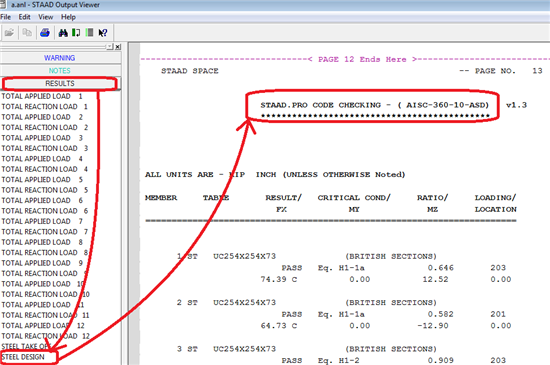
15. How to know the version of the design code which is being used by STAAD.Pro during the analysis?
The design code version which is being used by STAAD.Pro during the design phase is written in the Output file
16. How to see the displacement of only one particular node graphically?
1. Analyze the model and go to the Postprocessing mode, Node -> Displacements page.
2. If needed, turn on the node symbol (click Shift + K on your keyboard) and node numbers (Shift + N).
3. Go to the Results -> View Value menu.
4. In the Ranges tab select Ranges and enter the node number(s) for which you want to see the displacement.

5. Then go to the Node tab and select Nodal Displacement which you want to see. Click Annotate.

Now the displacement of only selected node will be seen on the screen. Similarly, beam force diagram values, beam maximum displacements, beam combined stresses and support reactions can be set.
17. What is the difference between the local and global deflection in the member query box?
Figures (1) and (2) show the local and global deflections of the beam #2 which is a part of the beam joining 2 columns:

Figure (1)

Figure (2)
Global deflection is the largest distance between (a) and (b) where:
(a) is the line joining the ends of the member in its un-deflected position (named as 'Original shape' in the figure (3));
(b) is the elastic curve of the member representing its deflected shape.
Local deflection is the largest distance between (c) and (d) where:
(c) is the line joining the ends of the member in its deflected position;
(d) is the elastic curve of the member representing its deflected shape.

Figure (3)
18. I am analyzing a large 3D structure. I changed the beta angle of one of the members to 90. I expected the MY and MZ for the two scenarios ( beta =0 and beta=90) to get interchanged. However that does not seem to happen. Why ?
The Mz and My would not simply get interchanged when you apply a beta angle to 90 for every situation. The same would be true if you are analyzing a beam in isolation without considering any effect from the rest of the structure. However when a beam is part of a bigger structure, the beam’s local stiffness in each direction would affect the global stiffness of the structure along each DOF. Depending on that there will be a redistribution of the forces which will result in different moments/shears.
19. How to get Member End Forces for a specific selection of beams?
The procedure of specifying the commands to report the member end forces is described in STAAD.Pro Help manual chapter 1.5.12:
Alternatively, one can use a Report Setup with specified Ranges (by group or simply typing in the member numbers in the Ranges field):
20. How do I change stress output units in the *.ANL output file? They are coming out as kN/m2. I want N/mm2.
The units of items reported in the analysis output file are based on the unit settings in the input command file ( editor ). The unit that is current at the time the relevant command triggering the output is processed, is used for the reporting. One can set the units appropriately using the editor ( Edit > Edit Input Command File ) as explained next. For example to get the support reactions and member forces reported in Newton and mm units one needs to enter the unit command before the print commands as shown next
…
PERFORM ANALYSIS
UNIT MM NEWTON
PRINT SUPPORT REACTIONS
PRINT MEMBER FORCES
…
Any other output printed in the ANL file following the above commands, would also be printed in the currently set units of Newton and mm.
21. How do I save a 3D rendered view (generated by the pyramid' icon)? I am able to do this for other views using View > View Management
As of now there is no way to save the 3D rendered view as a Saved View. However here are a couple of options that you may find useful
Right click on the 3D Rendered View and choose the Take Picture option. The picture is then saved and can be accessed from within Report Setup ( File > Report Setup ) and can be included as part of the report.
Instead of using a 3D Rendered View, you can plot a full section view ( right click inside the whole structure window and choose Labels > Structure > Full Sections ). This would be similar to the rendered view but the difference is, you would be able to save it through View > View Management
See Also
Structural Product TechNotes And FAQs
External Links
Bentley Technical Support KnowledgeBase
Comments or Corrections?
Bentley's Technical Support Group requests that you please confine any comments you have on this Wiki entry to this "Comments or Corrections?" section. THANK YOU!